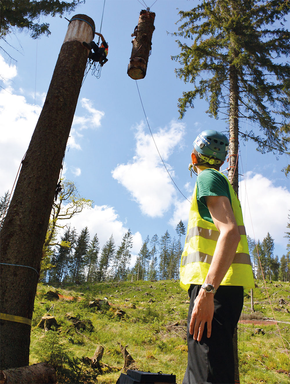
Lifting and resetting the test mass. The climber and mass were anchored with two fully independent systems. (Photo: Treemagineers Ltd)
In the course of the Health and Safety Executive Rigging Research, studies on rigging forces have been conducted by blocking the friction device and measuring forces in the block at the rigging point during simulated drops.
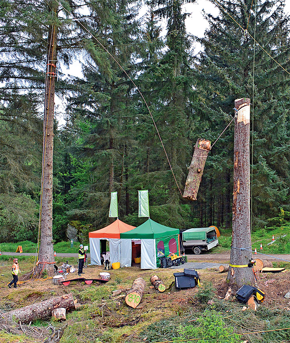
The recorded peak forces did not act parallel to the trunk but on average at an angle of 30° to 40° to the trunk axis. This creates a lateral bending moment that may cause a stem used as an anchor point to fail. The forces that occur at the rigging point (i.e. the block) exceeded the weight of the lowered section by an average of 8 to 12 times, and this factor decreases with increasing mass (HSE Rigging Report 2008). In more recent drop tests with Teufelberger Ropes, the Treemagineers used logs with a mass of up to 750kg, which is three times the mass of the biggest sections used in previous tests (Donzelli et al., 1998; HSE Rigging Report, 2008; Kane et al., 2009).

Snatching one of the medium-size test masses. All drops were static. The piece was tied off on the lowering device at the base of the tree. (Photo: Treemagineers Ltd)
The calculation of the forces that may occur at the anchor point during rigging operations is very complex, since numerous factors interact, and directly or indirectly affect the result. In addition to the mass of the lowered section, for example, the properties and length of the rope used also play an important role. For the experiments that are evaluated in Figure 1, only two types of rigging rope (double braid and kernmantle type) with 12mm and 14mm diameter were used. For those rigging systems, a rule of thumb for estimating the peak force in a worst-case scenario was derived.
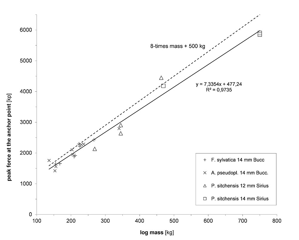
According to this rule, the force peak on the pulley can be assumed to be 8 times the mass of the trunk plus 500kp (kilopond [kp] is a force unit equal to the weight of 1kg). The load on the short end of the rope connected to the dropped section (lead of the line) can be estimated by dividing this value by 1.8 (HSE Rigging Report 2008). This rule is of course a simplification, but it underestimated the peak forces for trunk sections by less than 10% in 22 drops where the friction device was blocked. On the other hand, the result was only by a quarter too high at max in this series of tests.
The estimates by this rule of thumb should not be readily applied to other rigging scenarios and different kinds of rope. For example, the use of more rigid ropes with higher strength or other braiding may lead to greater peak forces. Other tests show that when lowering crown sections that are still in leaf, even with a locked friction device, peak forces do not exceed the forces generated during the slow ‘dynamic’ deceleration of trunk sections with similar mass. These relationships are further explained in Chapter 8 of the HSE Rigging Report.

Figure 1: Evaluation of forces generated at the rigging point (block) during 22 topping-down operations of trunk sections with locked friction device. Data on P. sitchensis courtesy of Treemagineers and Teufelberger Ropes; other data from the HSE Rigging Report.
Unfortunately, studies where a forcemeter is placed between the pulley and the anchor sling at the rigging point may be misleading (e.g. Donzelli et al., 1998; Kane et al., 2009). With this setup, the actual distance of fall is significantly extended, and much greater forces will be recorded than in real tree care operations. In the meantime, however, a load sensor has been developed by Straightpoint in cooperation with the Treemagineers, which is integrated into a rigging block and thus enables unadulterated measurements of the forces during rigging operations.
The rule of thumb is displayed as the dashed line; the solid line indicates the average correlation between mass of section and generated peak force at the rigging point. The R2 value of this trend (least squares method) is close to 0.97 which qualifies the mass of the log as a very good indicator of the peak force (cf. Kane et al., 2009). Yet, using different ropes, setting up different rigging systems with reduced rope length or performing different rigging operations may alter the actual forces significantly. Therefore, the rule of thumb can only be applied by with caution and must be adapted to the actual situation by an experienced and competent person.
Andreas Detter holds an engineering degree in landscape architecture and works as a consultant, researcher and trainer at Brudi & Partner TreeConsult, Germany. He was the primary author of the HSE Rigging Report (2008), and he is still involved in research projects that aim at increasing work safety for arborists during climbing and rigging. He frequently teaches and publishes in the fields of tree biomechanics, basics of the pulling test method, ancient and habitat tree management and cabling of tree crowns.
References
Detter, A., Cowell, C., McKeown, L., Howard, P. 2008. Evaluation of Current Rigging and Dismantling Practices Used in Arboriculture (Research Report No. RR668), HSE Books. Health and Safety Executive, Norwich, UK. www.hse.gov.uk/research/rrpdf/rr668.pdf.
Donzelli, P.S., Palmer, K., Tompkins, R., Longstaff, S. 1998. ‘Dynamic Forces of Rigging Operations in the Tree Care Industry’. Poster.
Kane, B., Brena, S., Autio, W. 2009. ‘Forces and stresses generated during rigging operations’. Arboriculture & Urban Forestry 35: 68–74.
Schwenteck, G. 2014. ‘Dynamic Loading of Rigging Ropes under Practical Conditions’ (Diploma thesis). Technical University Dresden, Germany.
Article taken from Issue 182 of the ARB Magazine.